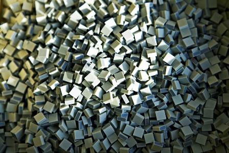
Technology
Recommend this page to friend Recommend this page     Print Print
 

Manufacturing


Process flow

A flow diagram of the manufacturing processes involved with piezo multilayer processing at Noliac is shown below. In the following each process is described.


Manufacturing process


Mixing


PZT powder with a specified particle size is mixed with additives and solvents. All accurate weighed after a well documented prescription.


[back to top]


Milling


The mixed materials are milled to achieve a very homogeneous suspension. The suspension is measured for viscosity and approved for tape casting.


[back to top]


Tape casting


The suspension is tape casted on a carrier foil and dried. The fired tape thickness is between 15 – 35 µm as standard. The green ceramic tape contains a large amount of binder materials, which makes the tape flexible and easy to handle in the following processes.


[back to top]


Stripping


The green ceramic tape is removed from the carrier foil and prepared for cutting.
 

[back to top]


Tape cutting


The tape is cut into square pieces of same size as the carrier blocks used in the subsequent processes. 


[back to top]


Build up


Build up multilayer components covers the repetition of three processes, stacking, printing and drying. Each process is repeated a number of times according to the number of active layers in the product. The output of the build up is a green ceramic block with internal electrodes.


[back to top]


Stacking


Layers of ceramic are placed on the carrier blocks before each print. The carrier-block is placed in a hydraulic press and each new ceramic layer is pressed gently against the ceramic layers underneath so the layers adhere.


[back to top]


Printing


Internal electrodes with predetermined patterns are printed with silkscreen on the top of the ceramic layer of the carrier-block. A suitable organic paste mixed with metal particles, e.g. platinum, is used for printing. For CMB it will be possible to mark the component with e.g. batch number or Customer ID.


[back to top]


Drying


The printed electrode is dried in a tunnel oven. Upon completion of the drying process the entire build-up procedure is repeated; stacking, printing and drying, according to the specifications of the current production batch.


[back to top]


Edge trimming


The edges on the green ceramic block are cut off for exact size, so the block will into the next step in processing. 


[back to top]


Lamination


The ceramic blocks are laminated at well defined pressure, temperature and time. At this process the layers are firmly laminated and brought in appropriate contact with each other. This process is very critical as either insufficient lamination or too much lamination has significant influence on the quality and accuracy of components. The chosen parameters for lamination must be well balanced for the binder system used. 


[back to top]


Dicing


After lamination, individual components are diced out of the green ceramic blocks. Dicing needs to be accurate matched to the pattern of the internal electrodes. Dicing might also be performed on fired ceramic.


[back to top]


Firing


The organic compounds in components, binder materials, additives and remaining solvents are removed by very slowly heating the green parts to a temperature, 500-700ºC, where the organic compounds decompose and evaporates from the ceramic. 


[back to top]


Sintering


In order for the ceramic particles to grow and merge into a solid polycrystalline structure the fired parts need to be heated to a temperature above 1000°C. The sintering is achieved at a protecting atmosphere in order to avoid loss of lead from the components. Several parameters have to be optimised with this process, e.g. temperature ramp rates, holding time and the condition of protective atmosphere. Sintered parts have essentially same form as they were fired, but will shrink to a denser component.


[back to top]


Termination


External electrodes are applied for making connection to the internal electrodes inside the component. After careful cleaning, components are applied with a conductive layer of silver or gold. The screen printing technique is commonly used.

A screen printed electrode, consisting of a mixture of metal powder (60-80 %) and a glass frit materials, provides the component with a fired electrode of 5 to 12 µm in layer thickness. Screen printed electrodes require a firing temperature between 600-800 °C depending on the material. Depending on the type of materiel used in this process, the paste will form a conductive layer with a good adhesion to the ceramic surface. 
 

[back to top]


Lapping


All CMA’s are lapped after termination. The surface roughness which can be achieved depends on the grain size of the abrasive used in the slurry. In Noliac our standard surface roughness for the lapped component is: Ra < 1.5 µm.


[back to top]


Polarisation


Activation of the piezoelectric ceramic properties is called the “poling” process. In order to obtain the piezoelectric effect in the PZT material, the dipoles in the grains must be aligned. This alignment is achieved in the poling process where a high electrical field, 2-3kV/mm, is applie