PAD7344
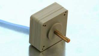
PAD7344 is a low-power motor designed for non-magnetic applications. PAD is a drive technology transforming the linear motion of high performance piezo multilayer actuators into a powerful and precisely controllable rotation. PAD7344 includes four multilayer piezo benders in a non-magnetic structure, providing high performance in a compact package.
Precision
- Positioning accuracy, repeatability and resolution (<6 arc seconds) without encoders/decoders
- No gearbox required/no backlash
- No overshooting
Dynamics
- High acceleration and deceleration without e-brake (low inertia)
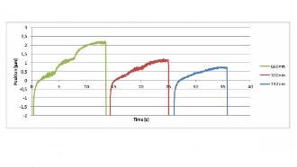
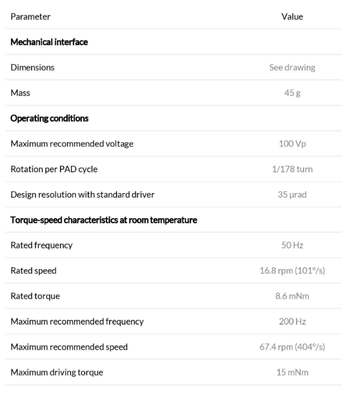
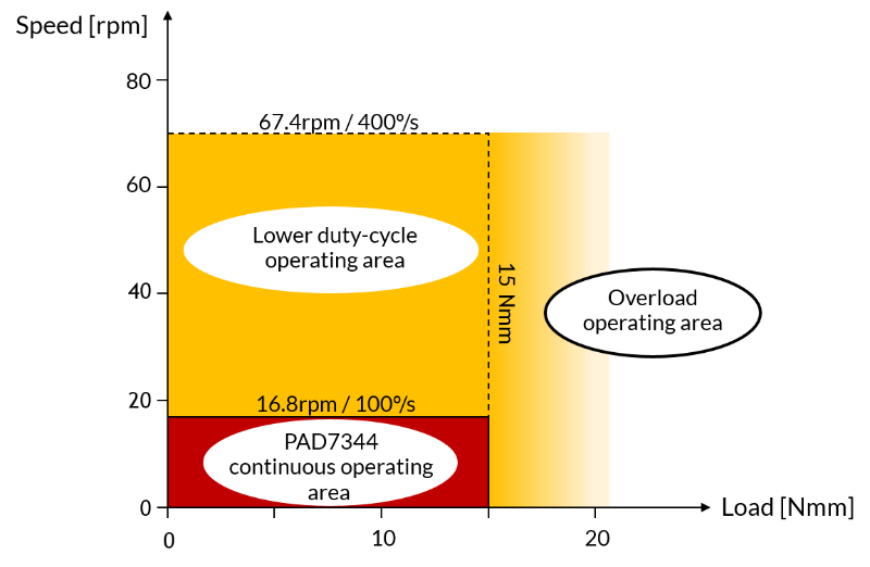
- Slow and precise motion possible (0 to 67 rpm)
- Speed is independent of load
Torque
- High torque without gearbox/no backlash (typical up to 15 mNm)
- Overload protection
Environment
- Non-magnetic, tested in 3T MRI at 20 cm from the centre of the bore
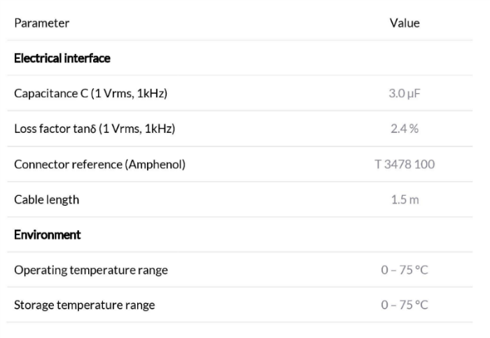
- Wider temperature range than other piezo motors (75°C)
Other
- Synchronization of multiple PADs possible
- No power consumption when holding a load
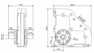
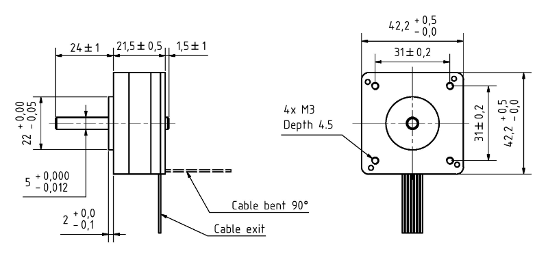
- Mechanical interface compatible with standard NEMA size 17
Download a 3D model of the motor (STP format)
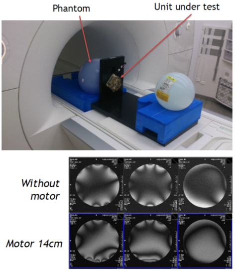
A PAD was tested in MRI environment. For this test, a SIEMENS 3T MRI is imaging an oil-filled “phantom” placed at the center of the bore and the interaction between motor and MRI is assessed.
The images show three orthogonal sections of the MRI measurement on the phantom, without motor (top) and with a PAD motor placed 14 cm from the center. The impact of the motor can be seen particularly on the image in the middle. It is less than the maximum acceptable distortion of one fringe.
In addition, it was also checked that:
- The operation of the motor has almost no impact on the imaging
- The imaging doesn’t affect the performance of the motor
- The attraction force due to the static magnetic field is well below the gravitational force
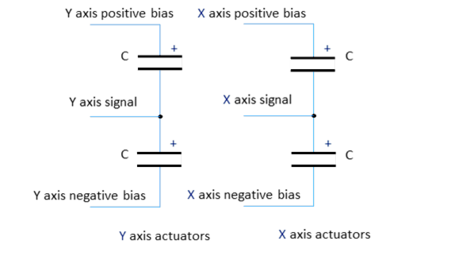
Signal definition
The internal wiring of PAD7344 can be described by this schematic:
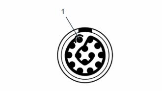
Pin-out of PAD7344
| Connector pin number | Signal |
|---|---|
| 1 | X axis negative bias (0V) |
| 2 | X axis signal |
| 3 | X axis positive bias (100V) |
| 4 | Y axis positive bias (100V) |
| 5 | Y axis signal |
| 6 | Y axis negative bias (0V) |
| 7 | Not connected |