


Piezoelectric materials exhibit non-linearity, hysteresis and creep. This section provides typical material data to understand and compensate these effects.
The are the topics covered by this page:
- Linearity: actuators, stacked actuators and benders
- Very high electric field material data - actuators, stacked actuators and benders
- Linearity - shear plates
- Hysteresis - actuators, stacked actuators and benders
- Hysteresis - shear plates
- Operation under reverse bias - actuators, stacked actuators and benders
- Creep
Linearity: Actuators (individual and stacked multilayer) and benders
The stroke versus applied voltage relationship for piezo electric actuators is not perfectly linear as predicted by the piezoelectric equations. Typical performances are shown in the following figures. As it can be seen, the extension vs voltage curve is actually slightly S-shaped. At low voltage, the curve for increasing voltage is concave upward and the shape is close to quadratic.
The example below shows the displacement during charging of an actuator using NCE57. More detailed curves can be found in the “hysteresis” section. Non-linearity implies that stroke at 1kV/mm is less than expected from the linear extrapolation using stroke at the maximum recommended field (which corresponds to 3kV/mm).

Non-linearity for NCE51
Very high electric field material data - actuators, stacked actuators and benders
In some applications, it is desirable to archive maximum strain from the piezo electric element only by applying a very high electric field. In some cases the maximum recommended field strength of 3kV/mm may be exceeded e.g. for short-term use applications or static applications. Operating field of 4kV/mm is normally acceptable, however testing is recommended.
The figure below shows how strain evolves with electric field for our different materials up to a maximum electrical field strength of 9kV/mm. The drawback of applying a very high electric field is that the actuator lifetime is reduced drastically.
The data in the figure are only of informative character and we recommend to contact our R&D before designing actuators based on very high electric field.

Strain vs. electric field for NCE46, NCE51F, NCE57 and NCE59
Linearity - shear plates
The peak to peak stroke versus peak applied voltage relationship for shear plates is not linear. Typical measurements are shown in the following figure. As it can be seen, the displacement increases when the actuator is used close to the maximum recommended voltage.
The polynomial trend follows the experimental relationship. With δ being the displacement, t the height of the actuator and E the applied electric field (Voltage/height):

.")
Experimental data and trend for two Noliac shear plates (CSAP02).
Hysteresis: Actuators (individual and stacked multilayer) and benders
All piezoelectric materials exhibit a mechanical hysteresis as the strain does not follow the same track upon charging and discharging. The hysteresis is expressed as the maximum difference between the two tracks divided by the maximum strain, as can be seen in the figure below. Hysteresis tends to decrease with ageing. If hysteresis is a problem for a specific application, it is common to use a model-based compensation or a feedback loop to compensate it. Feedback signal can be position, force or dielectric charge.

Figure showing the principle relationship between strain and electric field strength.

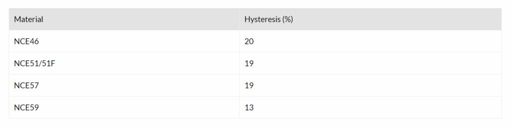
Figure showing the relationship for four different materials.
The hysteresis depends on the type of ceramics and the amplitude of the input signal and can vary from 13% to 20%.
On bending actuators the same hysteresis is present. However, because of the push-pull configuration, it has a symmetrical shape.
Hysteresis - shear plates
Due to their high non-linearity, shear plates exhibit much higher hysteresis than other actuator types. Hysteresis at full voltage amplitude is in the order of 35%. Reducing the amplitude of the voltage will reduce hysteresis.
")
Displacement vs. voltage for a Noliac shear plate CSAP02 (experimental data)
Operation under reverse bias: Actuators (individual and stacked multilayer) and benders
In addition to the normal hysteresis curve AB when the applied voltage is positive, the butterfly diagram CDEFG defines the behaviour of the material through a complete cycle of positive and negative operating electric fields. Negative electric fields produce negative strain along curve C until the depoling field (coercive field) where the extension suddenly turns positive following the curve D. The process is repeated along curves EFG when the electric field is made positive again. The “butterfly” diagram provides a complete characterization of the depoling and repoling process.
Most hard piezoelectric materials can only be fully poled or depoled at elevated temperatures so once poled, they can tolerate high reverse fields without difficulty.
We do not recommend operation under reverse field for quasi-static actuators. However, in some applications this can bring some additional strain. The drawbacks are the lower linearity, increased hysteresis and losses. In addition temperature must be monitored as the coercive field varies with temperature (refer to “thermal properties”).
Soft piezoelectric materials are easily depoled when subjected to an electrical field opposite to the poling direction. The effect of cycling between positive and negative voltages for various piezoelectric materials is shown in the following figures:


Strain vs. electric field for NCE46

Strain vs. electric field for NCE51

Strain vs. electric field for NCE57

Strain vs. electric field for NCE59
Creep
Piezoelectric materials exhibit a creep effect i.e. the material continues to expand for some time upon application of voltage. Correspondingly the material does not immediately return to the initial strain level after return to 0V. While creeping, the material continues to draw charge at very low levels. The creep effect for different actuator materials is compared in the following figure, where the maximum electric field is established after 1s, corresponding to the baseline for displacement (relative displacement = 1).
Creep always occurs in the same direction as the dimensional change produced by the voltage step. The effect is logarithmic so the additional expansion between 10s and 100s will be similar to the expansion obtained between 1s and 10s. For linear/stacked actuators, typical values are 4% per decade for NCE51/51F and 9% per decade for NCE46. Values are 2-3 times higher for bending actuators. Creep is related to the long-time average that the actuator has experienced in its life.

Creep for NCE46, NCE51, /NCE57 and NCE59
Sign up for our webinars
Our free 1.5 hour webinars follow the same structure as our tutorials.
A piezo partner - what do we mean by that

We give you a competitive advantage by using our extensive knowledge to customize and optimize your piezo products. Thus, we will be your long-term piezo partner. Send your request today.
Search tool
Performance
Dimensions
Value
Max operating voltage / V
Min
Min free stroke / µm
Min
Min estimated blocking force / N
Min
Min
Max
Length or outer diameter / mm
Min
Max
Width or inner diameter / mm
Min
Max
Max height / mm
Max
Product category
Choose here...
- Plate actuators
- Plate stacks
- Ring actuators
- Ring stacks
- Plate benders
- Ring benders
- Shear plate actuators
- Shear stacks
- 2D actuators
- High temperature stacks
- Damage tolerant stacks
Material
Choose here...
- NCE51
- NCE51F
- NCE46
- NCE57
- NCE40
- NCE41
- NCE55
- NCE56
- NCE59
- NCE81
- 0,00
- AA
- Material
- Type
- 0.00
Search
Clear
Next