


Aging
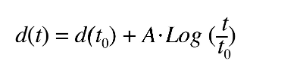
Change of material properties with time. Aging of piezoelectric ceramic occurs very rapidly in the first few hours after poling. After a few days the changes in the material properties are very small and decrease logarithmically. Indeed in ferroelectrics, the aging of piezoelectric properties is often logarithmic. As seen below.
Where to is an arbitrary time when the measurement has started, and A is the “aging rate” constant, specific to the composition, the microstructure, and the processing history of the element.
An origin of aging is in internal stresses such as those built in the material during poling. These stresses may be relaxed by domain reorientation during time. Another source of aging is point defects that exist in many piezoelectric ceramics (vacancies of lead and of oxygen) and are mobile with time and may build internal fields that restrict domain wall movements. Space charge in grain boundaries may also contribute to aging.
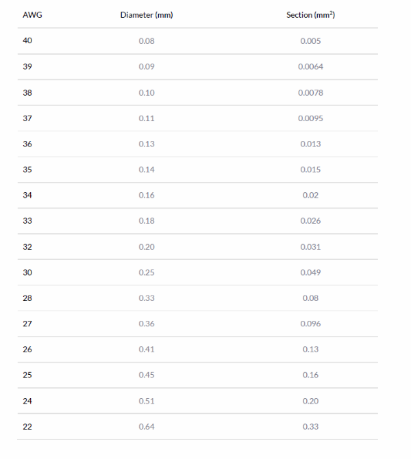
AWG
AWG (American wire gauge) is a standard wire gauge system for the diameters of wires. These are the AWG sizes relevant for Noliac products.
Axes
Similarly to most materials, piezoelectric ceramic is elastic, i.e. it follows Hooke’s law. In other words, strain is proportional to stress. In addition, the piezoelectric effect can be represented as an additional term in the relationship, in a first approach proportional to the electrical field. This can be visualized as a relationship on two axes. This ”bilinear” relationship is valid at the material level (strain, stress, field) whatever the orientation of the material and can be extended to all types of actuators (displacement, force, voltage). As a result, any piezoelectric actuator can be described as a spring with a characteristic that can be shifted through the application of a voltage. Or in a displacement vs. force graph.
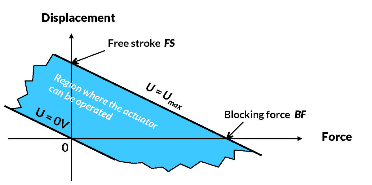
Blocking force
All piezoelectric actuators can be described as a spring with a characteristic that can be shifted through the application of a voltage. Or in a displacement vs. force graph. It is an industry standard to describe this behavior using the terms ”free stroke” and ”blocking force”. Free stroke is the vertical distance between the curves while blocking force is the horizontal distance between the curves. Note that in this model, the stiffness of the actuator is (blocking force)/(free stroke) and is supposed constant. This characteristic might be limited by a minimum/maximum force allowable on the actuator. However, these parameters are not necessarily related to the blocking force.
See Axis in this dictionary as well.
Further reading: Constitutive equations
Bus wire
A wire with multiple bends soldered on stacked ceramic multilayer actuators to electrically connect all the multilayer actuators in the stack.
Capacitance
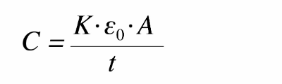
The capacitance is a quantity dependent on the type of material and its dimensions. Capacitance is calculated by multiplying the relative dielectric constant K by the permittivity of free space εo (εo=8.9 x 10⁻¹² Farads/meter) and electrode surface area A, then dividing by the thickness t separating the electrodes. Units are expressed in farads. See the formula below.
Piezoelectric actuators with many thin dielectric layers connected in parallel (multilayers) can be of quite high capacitance, especially those for low operating voltage. A capacitance in the range of 1-10 µF is not unusual. This has to be taken into consideration when developing the driving electronics, or matching an actuator to existing driving electronics.
Please note
The electrical capacitances stated are measured for “small signal values”. Capacitance of piezoelectric actuators varies with voltage, temperature and load. Therefore the stated capacitances are only a rough number. Capacitance data are needed to value the electrical currents or powers required for a distinct dynamic reaction. Please take therefore into account at least a factor 1.5, when checking for a proper power supply.
Closed loop control
The actuator is used with a position sensor, providing feedback to the position servo controller compensating for non-linearity, hysteresis and creep of the piezoelectric actuator.
Coupling factor
A dimensionless number defined as the square root of the ratio of energy stored in mechanical deformation to the electrical energy needed to produce that deformation.
Creep
Piezoelectric materials exhibit a creep effect i.e. the material continues to expand for some time upon application of voltage. Correspondingly the material does not immediately return to the initial strain level after return to 0V. While creeping, the material continues to draw charge at very low levels. The creep effect for different actuator materials is compared in the following figure, where the maximum electric field is established after 1s, corresponding to the baseline for displacement (relative displacement = 1).
Creep always occurs in the same direction as the dimensional change produced by the voltage step. The effect is logarithmic so the additional expansion between 10s and 100s will be similar to the expansion obtained between 1s and 10s. For linear/stacked actuators, typical values are 4% per decade for NCE51/51F and 9% per decade for NCE46. Values are 2-3 times higher for bending actuators. Creep is related to the long-time average that the actuator has experienced in its life.
Curie temperature
As the operating temperature increases, it gets easier to depole the piezoelectric material. Complete and permanent depoling occurs at the material's Curie temperature. Each ceramic has its own Curie point. When the ceramic element is heated above the Curie point, all piezoelectric properties are lost. In practice, the operating temperature must be substantially below the Curie point.
D constant
A constant that represents the piezoelectric sensitivity by relating the mechanical strain with applied electric field. It is defined as the ratio of strain to electric field.
Dielectric constant, relative
The ratio of the permitivity of the material ε to the permitivity of free space ε0 at low frequencies well below any mechanical resonance of the structure.
The relative dielectric constant is important because it affects the capacitance of piezoelectric component and therefore the electric current required to drive them at high frequencies.
Displacement
Displacement refers to the change of position of an object.
Dissipation factor
The dissipation factor is a number that specifies the dielectric losses inherent in a piezoelectric material. It is defined as the tangent of the loss factor (tan δ), or the ratio of effective series resistance to the effective series reactance, expressed in percent. The dissipation factor is usually specified for low electric fields and at a frequency of 1000 Hz. In static operation virtually no heat is generated with voltage applied, but when the voltage is modulated at high frequency heat is generated inside the material in proportion to the dissipation factor. The associated temperature rise is often the limitation on the power handling capability of the material.
Doped
The term doped refers to the distinction between the characteristics of hard doped and soft doped piezoceramic materials.
Learn more about hard and soft doped piezoceramic materials
Free displacement
Free displacement is the displacement you obtain from a piezo when it is "free" (i.e. without mechanical load).
See also Displacement in this dictionary.
Free stroke
All piezoelectric actuators can be described as a spring with a characteristic that can be shifted through the application of a voltage. Or in a displacement vs. force graph. It is an industry standard to describe this behavior using the terms ”free stroke” and ”blocking force”. Free stroke is the vertical distance between the curves while blocking force is the horizontal distance between the curves. Note that in this model, the stiffness of the actuator is (blocking force)/(free stroke) and is supposed constant. This characteristic might be limited by a minimum/maximum force allowable on the actuator. However, these parameters are not necessarily related to the blocking force.
See Axis in this dictionary as well.
Further reading: Constitutive equations
Hard
The piezoceramic material can be either hard or soft. Hard material can withstand high level of electrical excitation and mechanical stress, and are not easy poled or depolarised except at elevated temperature. However this stability is accompanied by small d constants. If intending to use piezoelectric actuators in dynamic operation for instance, e.g. piezoelectric motor, it is strongly recommended to use actuators based on a hard piezoceramic material, which has a factor 10 lower dielectric losses than “soft” materials.
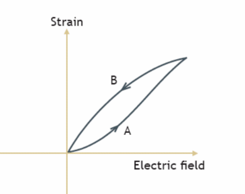
Hysteresis
All piezoelectric materials exhibit a mechanical hysteresis as the strain does not follow the same track upon charging and discharging. The hysteresis is expressed as the maximum strain divided by the maximum difference between the two tracks as can be seen in the figure below. Hysteresis tends to decrease with ageing. If hysteresis is a problem for a specific application, it is common to use a feedback loop to compensate it. Feedback signal can be position, force or dielectric charge.
Read more about hysteresis
Maximum free displacement
Displacement measured at room temperature, with no mechanical load and at maximum recommended voltage.
Maximum recommended operating temperature
Maximum temperature the actuator should be exposed to during operation or handling – even short term.
Mechanical quality factor QM
QM factor is the ratio of the reactance to the resistance in the series equivalent circuit representing the piezoelectric resonator. The Qm factor is calculated using the formula below:
QM = mechanical quality factor
fr = resonance frequency [Hz]
fa = anti-resonance frequency [Hz]
Zm= minimum impedance at fr [ohm]
C = capacitance [F]

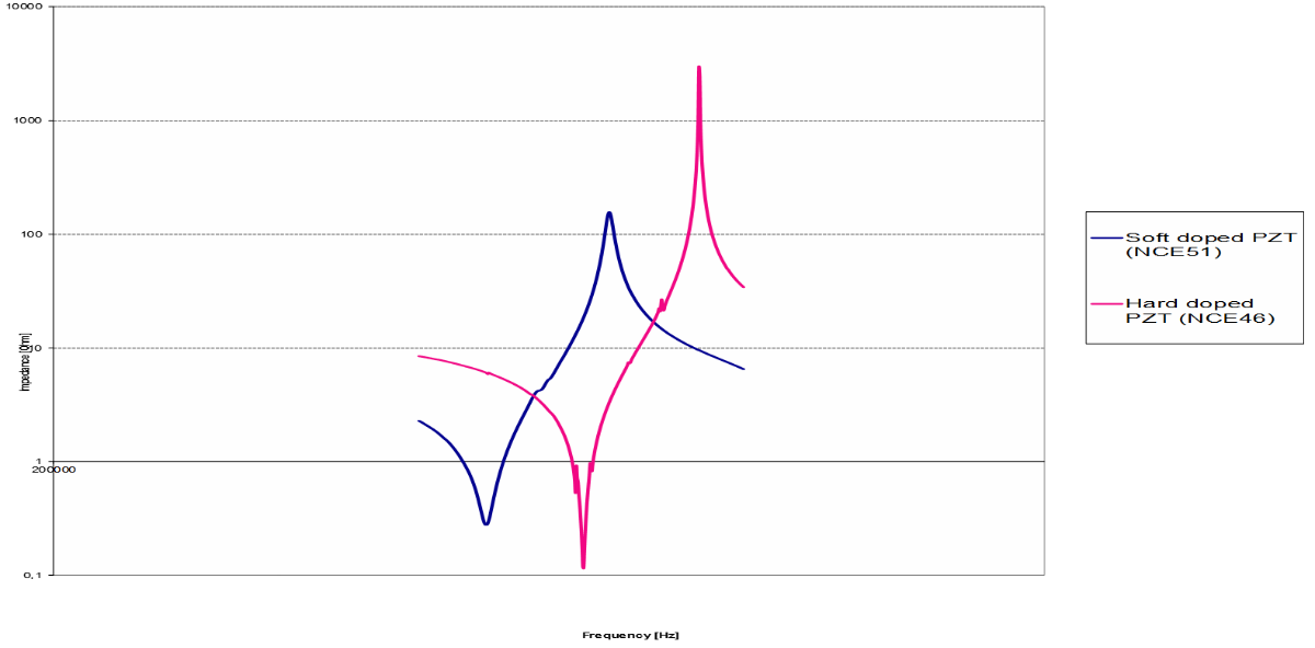
The figure shows a comparison between an actuator with the dimensions 5 mm x 5 mm x 2 mm made by soft doped piezoceramic material (NCE51) and hard doped piezoceramic material (NCE46).
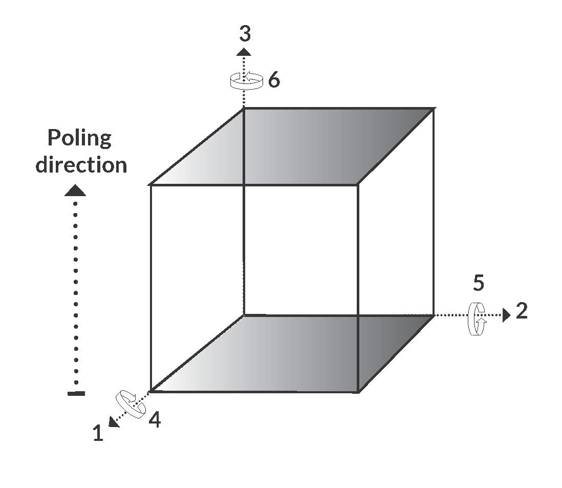
Monolayer
The most common configuration of a monolayer component is with the electrodes perpendicular to the poling direction. Here, the application of an electric field on the surface electrodes will lead to a contraction in directions "1" and "2" together with an expansion in direction "3". Monolayer components are available as rectangular plates, discs, rings, tubes. As actuators, they provide micrometer displacement but require high voltage for operation (kV range).
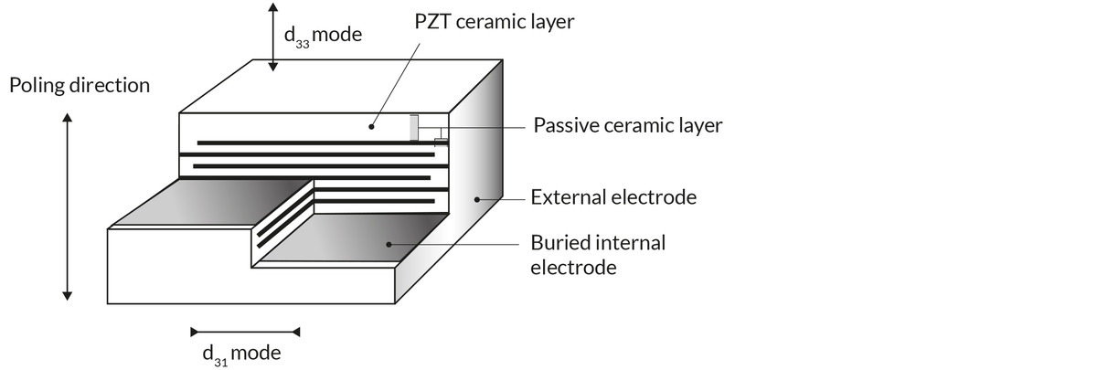
Multilayer
A multilayer component is composed of several thin layers of piezoelectric material, alternating with internal electrodes. Internal electrodes are successively positive and negative. All positive electrodes are connected by one external electrode on one side of the component; negative electrodes are connected on the other side of the component. Free displacement is up to 5 µm with blocking force in the range 200 to 10000 N depending on material and cross-section.
Open loop control
The actuator is used without a position sensor. Displacement roughly corresponds to the drive voltage. Creep, non-linearity and hysteresis are not compensated for.
Piezoceramic material
Ceramics are inorganic non-metallic materials. Piezoceramic materials differ from piezoelectric crystals in that they must undergo a poling procedure for the piezoelectric phenomenon to occur. For each material there is a characteristic Curie temperature. Above the Curie temperature electric dipoles inside the material exist in random orientations. When a strong electric field is applied they become aligned in the direction of the field and remain partially aligned after the field is removed, provided the material is first cooled well below its Curie temperature. In this state the ceramic is said to be poled. When the poled ceramic is subjected to a small electric field the dipoles respond collectively to produce a macroscopic expansion along the poling axis and contraction perpendicular to it.
Although there are several types of piezoelectric ceramic materials available today, most can be placed into one of two general categories: “Hard” materials and “soft” materials.
Hard material> can withstand high level of electrical excitation and mechanical stress, and are not easy poled or depolarised except at elevated temperature. However this stability is accompanied by small d constants. If intending to use piezoelectric actuators in dynamic operation for instance, e.g. piezoelectric motor, it is strongly recommended to use actuators based on a hard piezoceramic material, which has a factor 10 lower dielectric losses than “soft” materials.
Soft material feature high sensitivity and permittivity and are well suited for static applications. They produce larger displacements because their d constants are greater. However when operated in dynamic mode soft piezoceramic material types suffer from high dielectric losses and high dissipation factors which may limit the ability to drive them at high frequencies.
PZT
An acronym for Lead Zirconate Titanate.
Recommended voltage range
The actuators should not be exposed to any voltage outside this range during operation – even on short term.
Soft
The piezoceramic material can be either hard of soft. Soft material feature high sensitivity and permittivity and are well suited for static applications. They produce larger displacements because their d constants are greater. However when operated in dynamic mode soft piezoceramic material types suffer from high dielectric losses and high dissipation factors which may limit the ability to drive them at high frequencies.
Strain
The strain is the ratio of the change in length to the length.
Wire
The wires soldered to the stacked multilayer actuators are single or multi-core leads with a specified length and a gauge using AWG.
A piezo partner - what do we mean by that

We give you a competitive advantage by using our extensive knowledge to customize and optimize your piezo products. Thus, we will be your long-term piezo partner. Send your request today.
Search tool
Performance
Dimensions
Value
Max operating voltage / V
Min
Min free stroke / µm
Min
Min estimated blocking force / N
Min
Min
Max
Length or outer diameter / mm
Min
Max
Width or inner diameter / mm
Min
Max
Max height / mm
Max
Product category
Choose here...
- Plate actuators
- Plate stacks
- Ring actuators
- Ring stacks
- Plate benders
- Ring benders
- Shear plate actuators
- Shear stacks
- 2D actuators
- High temperature stacks
- Damage tolerant stacks
Material
Choose here...
- NCE51
- NCE51F
- NCE46
- NCE57
- NCE40
- NCE41
- NCE55
- NCE56
- NCE59
- NCE81
- 0,00
- AA
- Material
- Type
- 0.00
Search
Clear
Next