CTS CorporationCTS Corporation
NAC2124-Hxx

NAC2124-Hxx

Products in this category
  • NAC2121-Hxx
  • NAC2122-Hxx
  • NAC2123-Hxx
  • NAC2124-Hxx
  • NAC2125-Hxx

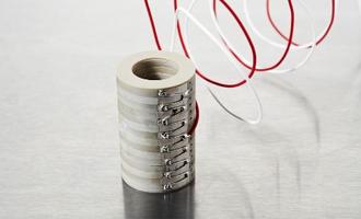
Noliac ring stack actuator NAC2124-Hxx (height in mm – Hxx) is based on the multilayer actuator NAC2124 and can be stacked to match you requirements. The standard range of NAC2124-Hxx is produced in a height between 4-150 mm. The ring stack provides a stroke in a range between 3.3 and 244.2 µm and blocking force up to 4750 N depending on the height of the stack.

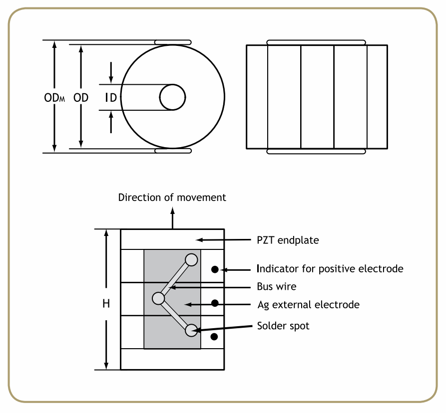
Specifications Drawings Mount and connect Wires
Specifications
Attributes
Value
Tolerance
Length / outer diameter
15 mm
+0.65/-0.45 mm
Width / inner diameter
9 mm
+0.30/-0.50 mm
Max width / outer diameter max
16.8 mm
Height
4 — 150 mm
+/-0.2 mm or 1% (whichever is largest)
Operating voltage, max.
200 V
Free stroke, max.
3.3 — 244.2 µm
+/- 15%
Blocking force, max.
4750 N
+/-20%
Capacitance
460-33950 nF
+/- 15%
Stiffness
1439-19 N/µm
+/-20%
Maximum operating temperature
150 °C
Material
Unloaded resonance frequency
>248k - 7 k Hz
Electrodes
Screen-printed Ag and soldered bus wire (option: glued connections)
Remarks
-

Stack options

Height
Stroke
Capacitance
Height
4 mm
Stroke
3.3 µm
Capacitance
460 nF
Height
6 mm
Stroke
6.6 µm
Capacitance
920 nF
Height
8 mm
Stroke
9.9 µm
Capacitance
1380 nF
Height
10 mm
Stroke
13.2 µm
Capacitance
1840 nF
Height
12 mm
Stroke
16.5 µm
Capacitance
2300 nF
Height
14 mm
Stroke
19.8 µm
Capacitance
2750 nF
Height
16 mm
Stroke
23.1 µm
Capacitance
3210 nF
Height
18 mm
Stroke
26.4 µm
Capacitance
3670 nF
Height
20 mm
Stroke
29.7 µm
Capacitance
4130 nF
Height
22 mm
Stroke
33 µm
Capacitance
4590 nF
Height
24 mm
Stroke
36.3 µm
Capacitance
5050 nF
Height
26 mm
Stroke
39.6 µm
Capacitance
5510 nF
Height
28 mm
Stroke
42.9 µm
Capacitance
5970 nF
Height
30 mm
Stroke
46.2 µm
Capacitance
6430 nF
Height
32 mm
Stroke
49.5 µm
Capacitance
6890 nF
Height
34 mm
Stroke
52.8 µm
Capacitance
7340 nF
Height
36 mm
Stroke
56.1 µm
Capacitance
7800 nF
Height
38 mm
Stroke
59.4 µm
Capacitance
8260 nF
Height
40 mm
Stroke
62.7 µm
Capacitance
8720 nF
Height
42 mm
Stroke
66 µm
Capacitance
9180 nF
Height
44 mm
Stroke
69.3 µm
Capacitance
9640 nF
Height
46 mm
Stroke
72.6 µm
Capacitance
10100 nF
Height
48 mm
Stroke
75.9 µm
Capacitance
10560 nF
Height
50 mm
Stroke
79.2 µm
Capacitance
11020 nF
Height
52 mm
Stroke
82.5 µm
Capacitance
11480 nF
Height
54 mm
Stroke
85.8 µm
Capacitance
11930 nF
Height
56 mm
Stroke
89.1 µm
Capacitance
12390 nF
Height
58 mm
Stroke
92.4 µm
Capacitance
12850 nF
Height
60 mm
Stroke
95.7 µm
Capacitance
13310 nF
Height
62 mm
Stroke
99 µm
Capacitance
13770 nF
Height
64 mm
Stroke
102.3 µm
Capacitance
14230 nF
Height
66 mm
Stroke
105.6 µm
Capacitance
14690 nF
Height
68 mm
Stroke
108.9 µm
Capacitance
15150 nF
Height
70 mm
Stroke
112.2 µm
Capacitance
15610 nF
Height
72 mm
Stroke
115.5 µm
Capacitance
16070 nF
Height
74 mm
Stroke
118.8 µm
Capacitance
16520 nF
Height
76 mm
Stroke
122.1 µm
Capacitance
16980 nF
Height
78 mm
Stroke
125.4 µm
Capacitance
17440 nF
Height
80 mm
Stroke
128.7 µm
Capacitance
17900 nF
Height
82 mm
Stroke
132 µm
Capacitance
18360 nF
Height
84 mm
Stroke
135.3 µm
Capacitance
18820 nF
Height
86 mm
Stroke
138.6 µm
Capacitance
19280 nF
Height
88 mm
Stroke
141.9 µm
Capacitance
19740 nF
Height
90 mm
Stroke
145.2 µm
Capacitance
20200 nF
Height
92 mm
Stroke
148.5 µm
Capacitance
20660 nF
Height
94 mm
Stroke
151.8 µm
Capacitance
21110 nF
Height
96 mm
Stroke
155.1 µm
Capacitance
21570 nF
Height
98 mm
Stroke
158.4 µm
Capacitance
22030 nF
Height
100 mm
Stroke
161.7 µm
Capacitance
22490 nF
Height
102 mm
Stroke
165 µm
Capacitance
22950 nF
Height
104 mm
Stroke
168.3 µm
Capacitance
23410 nF
Height
106 mm
Stroke
171.6 µm
Capacitance
23870 nF
Height
108 mm
Stroke
174.9 µm
Capacitance
24330 nF
Height
110 mm
Stroke
178.2 µm
Capacitance
24790 nF
Height
112 mm
Stroke
181.5 µm
Capacitance
25250 nF
Height
114 mm
Stroke
184.8 µm
Capacitance
25700 nF
Height
116 mm
Stroke
188.1 µm
Capacitance
26160 nF
Height
118 mm
Stroke
191.4 µm
Capacitance
26620 nF
Height
120 mm
Stroke
194.7 µm
Capacitance
27080 nF
Height
122 mm
Stroke
198 µm
Capacitance
27540 nF
Height
124 mm
Stroke
201.3 µm
Capacitance
28000 nF
Height
126 mm
Stroke
204.6 µm
Capacitance
28460 nF
Height
128 mm
Stroke
207.9 µm
Capacitance
28920 nF
Height
130 mm
Stroke
211.2 µm
Capacitance
29380 nF
Height
132 mm
Stroke
214.5 µm
Capacitance
29840 nF
Height
134 mm
Stroke
217.8 µm
Capacitance
30290 nF
Height
136 mm
Stroke
221.1 µm
Capacitance
30750 nF
Height
138 mm
Stroke
224.4 µm
Capacitance
31210 nF
Height
140 mm
Stroke
227.7 µm
Capacitance
31670 nF
Height
142 mm
Stroke
231 µm
Capacitance
32130 nF
Height
144 mm
Stroke
234.3 µm
Capacitance
32590 nF
Height
146 mm
Stroke
237.6 µm
Capacitance
33050 nF
Height
148 mm
Stroke
240.9 µm
Capacitance
33510 nF
Height
150 mm
Stroke
244.2 µm
Capacitance
33970 nF
Drawings
Noliac - Your Piezo Partner
Mount and connect

Mounting
The actuators are usually grinded on top and bottom surfaces (perpendicular to the direction of expansion) in order to obtain flat and parallel surfaces for mounting. The actuators may be mounted either by mechanical clamping or gluing.

Avoiding short circuit can either be achieved by: 

  • Adding Kapton foil on the metallic surfaces.
  • Having inactive ceramic plates between the actuator and the metal plate.

Stacked actuators are manufactured with top and bottom insulating ceramic end-plates.

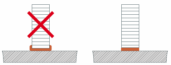
If glued, it is important to ensure a very thin glue line between the actuator and the substrate. It is recommended that a pressure, e.g. 2-5 MPa, is applied during the curing process.

To avoid significant loss of performance, the mounting of the actuators should avoid mechanical clamping and/or gluing on the sides of the actuator.

During manufacturing or handling, minor chips on the end-plates can appear. Minor chips cannot be avoided, but such chips do not affect performance.

Electrical connection

External electrodes

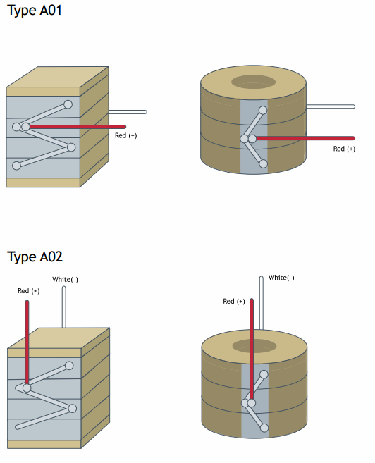
The external electrodes are screen printed silver as standard. Other materials, e.g. gold or silver/palladium are available on request. The positive electrode is indicated by a black spot.

Electrical connection to the external electrodes can be achieved by mechanical contacts, soldering, gluing with electrically conductive glues or wire bonding.

Mechanical connections

Mechanical connections can be arranged by e.g. copper springs contacted to the external electrodes. It is recommended to use external electrodes of gold in order to eliminate oxidation of the electrodes.

Soldering

Soldering electrical wires to the screen-printed silver electrode makes an excellent and time-stable connection. In order to avoid challenges with wetting the solder on the silver surface, always clean the external electrodes with a glass brush or steel wool.
Noliac - Your Piezo Partner

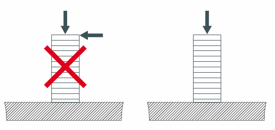
The actuators may only be stressed axially. Tilting and shearing forces must be avoided.
Noliac - Your Piezo Partner

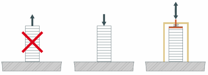
The actuators without preload are sensitive to pulling forces. It is recommended to apply a pre-load in order to optimize the performances of the actuators.

Noliac - Your Piezo Partner

For linear actuators it is recommended not to use a metal plate on top and bottom in order to avoid short circuit.
Noliac - Your Piezo Partner

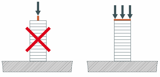
The force must be applied on the full surface of the actuator in order to assure a good load distribution.
Noliac - Your Piezo Partner

Epoxy glues are well suited for gluing piezoceramics.

Wires

When you order actuators from Noliac, you can have wires fitted to save time and money. However, you should consider these parameters, when you select a wire for connection: 

  • Operation voltage
  • Intensity of current
  • Operating temperature
  • Environment for example vacuum

We recommend Teflon wires
Teflon wires can stand temperatures above 200 ºC, whereas PVC wires only resist temperatures up to 80 ºC. In tough operating conditions or in vacuum, it is recommended always to use Teflon isolated wire to guarantee the proper performance of PZT-elements.

Wire thickness (AWG)
The wire thickness (AWG) is determined by the current that has to be transmitted to and from the PZT-element. The required current is determined by the capacitance of the PZT-element, the maximum driving frequency and the maximum voltage Up-p.

Noliac - Your Piezo Partner

Related products

Related tutorials and technical support

A piezo partner - what do we mean by that

Request for quote

We give you a competitive advantage by using our extensive knowledge to customize and optimize your piezo products. Thus, we will be your long-term piezo partner. Send your request today.

First name *
Last name *
Company *
Industry *
Email *
Phone
Country *
City
Choose product
Description
Please enter the result of the equation:
7 + 8 =
Close
Request for quote

Search tool

Performance Dimensions
Value
Max operating voltage / V
Min
Min free stroke / µm
Min
Min estimated blocking force / N
Min
Min
Max
Length or outer diameter / mm
Min
Max
Width or inner diameter / mm
Min
Max
Max height / mm
Max
Product category
Choose here...
  • Plate actuators
  • Plate stacks
  • Ring actuators
  • Ring stacks
  • Plate benders
  • Ring benders
  • Shear plate actuators
  • Shear stacks
  • 2D actuators
  • High temperature stacks
  • Damage tolerant stacks
Material
Choose here...
  • NCE51
  • NCE51F
  • NCE46
  • NCE57
  • NCE40
  • NCE41
  • NCE55
  • NCE56
  • NCE59
  • NCE81
  • 0,00
  • AA
  • Material
  • Type
  • 0.00
Search Clear
Next

Search on Noliac