NAC2122-Hxx
- NAC2121-Hxx
- NAC2122-Hxx
- NAC2123-Hxx
- NAC2124-Hxx
- NAC2125-Hxx
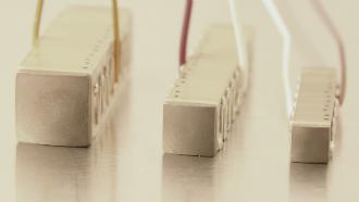
Noliac ring stack actuator NAC2122-Hxx (height in mm – Hxx) is based on the multilayer actuator NAC2122 and can be stacked to match you requirements. The standard range of NAC2122-Hxx is produced in a height between 4-80 mm. The ring stack provides a stroke in a range between 3.3 and 128.7 µm and blocking force up to 1810 N depending on the height of the stack.
Stack options
Mounting
The actuators are usually grinded on top and bottom surfaces (perpendicular to the direction of expansion) in order to obtain flat and parallel surfaces for mounting. The actuators may be mounted either by mechanical clamping or gluing.
Avoiding short circuit can either be achieved by:
- Adding Kapton foil on the metallic surfaces.
- Having inactive ceramic plates between the actuator and the metal plate.
Stacked actuators are manufactured with top and bottom insulating ceramic end-plates.
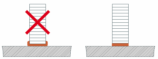
If glued, it is important to ensure a very thin glue line between the actuator and the substrate. It is recommended that a pressure, e.g. 2-5 MPa, is applied during the curing process.
To avoid significant loss of performance, the mounting of the actuators should avoid mechanical clamping and/or gluing on the sides of the actuator.
During manufacturing or handling, minor chips on the end-plates can appear. Minor chips cannot be avoided, but such chips do not affect performance.
Electrical connection
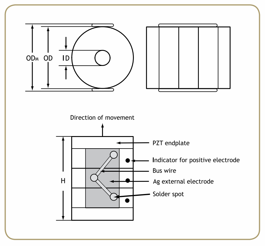
External electrodes
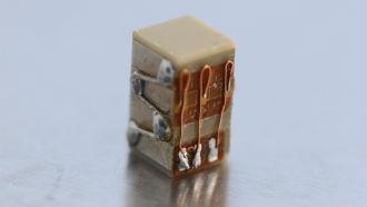
The external electrodes are screen printed silver as standard. Other materials, e.g. gold or silver/palladium are available on request. The positive electrode is indicated by a black spot.
Electrical connection to the external electrodes can be achieved by mechanical contacts, soldering, gluing with electrically conductive glues or wire bonding.
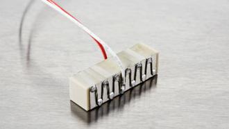
Mechanical connections
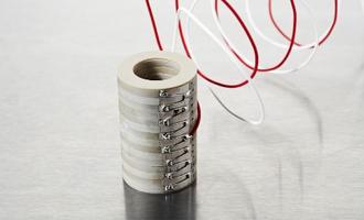
Mechanical connections can be arranged by e.g. copper springs contacted to the external electrodes. It is recommended to use external electrodes of gold in order to eliminate oxidation of the electrodes.
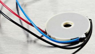
Soldering
Soldering electrical wires to the screen-printed silver electrode makes an excellent and time-stable connection. In order to avoid challenges with wetting the solder on the silver surface, always clean the external electrodes with a glass brush or steel wool.
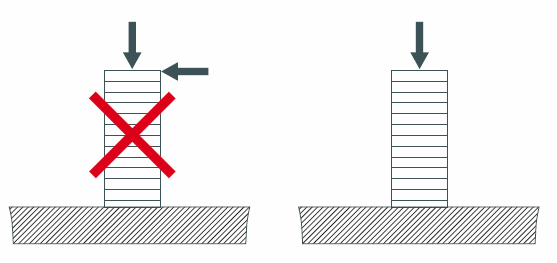
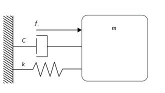
The actuators may only be stressed axially. Tilting and shearing forces must be avoided.
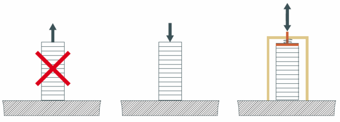
The actuators without preload are sensitive to pulling forces. It is recommended to apply a pre-load in order to optimize the performances of the actuators.
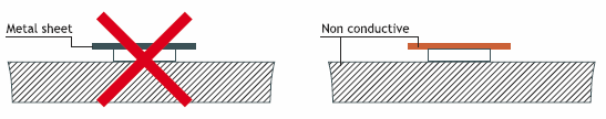
For linear actuators it is recommended not to use a metal plate on top and bottom in order to avoid short circuit.
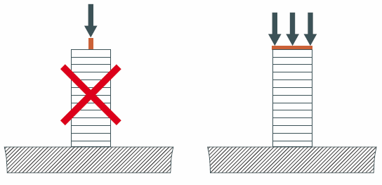
The force must be applied on the full surface of the actuator in order to assure a good load distribution.
Epoxy glues are well suited for gluing piezoceramics.
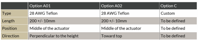
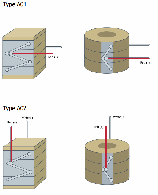
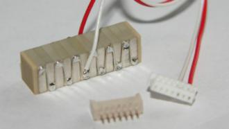
When you order actuators from Noliac, you can have wires fitted to save time and money. However, you should consider these parameters, when you select a wire for connection:
- Operation voltage
- Intensity of current
- Operating temperature
- Environment for example vacuum
We recommend Teflon wires
Teflon wires can stand temperatures above 200 ºC, whereas PVC wires only resist temperatures up to 80 ºC. In tough operating conditions or in vacuum, it is recommended always to use Teflon isolated wire to guarantee the proper performance of PZT-elements.
Wire thickness (AWG)
The wire thickness (AWG) is determined by the current that has to be transmitted to and from the PZT-element. The required current is determined by the capacitance of the PZT-element, the maximum driving frequency and the maximum voltage Up-p.